Blog

What Is a Cable Assembly and How to Choose One?

A cable assembly is more than a cable with connectors attached. It is a tested electrical and mechanical system, built for a specific space, signal, load, and service life. Inside a control cabinet, for example, a small wiring harness may bend around a sharp corner, face vibration, and carry power beside sensitive data lines. Each detail can affect safety, performance, and maintenance.

Steve Lampen, a longtime Belden technical expert and author on cabling, offers a useful reminder: “The cable is only as good as its weakest link.” That link might be a poorly crimped terminal, an unsuitable jacket, or a connector exposed to moisture. The point sounds simple. It is often ignored.

This guide explains what a cable assembly includes and how to select one with greater confidence. It considers conductor material, insulation, shielding, connector style, current rating, voltage, bend radius, temperature, and environmental exposure. It also examines testing, labeling, customization, and supplier quality controls. A lower purchase price can look attractive, but replacement labor may cost far more. That calculation is easy to miss.

Real selection work is rarely perfect. A drawing may omit the bend radius. A prototype may pass inspection but fail after repeated flexing. Therefore, buyers should confirm application conditions, review technical data, and request sample testing when the consequences of failure are serious. The right cable assembly is not simply the one that fits today. It should remain dependable after installation, movement, heat, and time.
What Is a Cable Assembly and How to Choose One?

What a Cable Assembly Is and What It Does

What Is a Cable Assembly and How to Choose One?

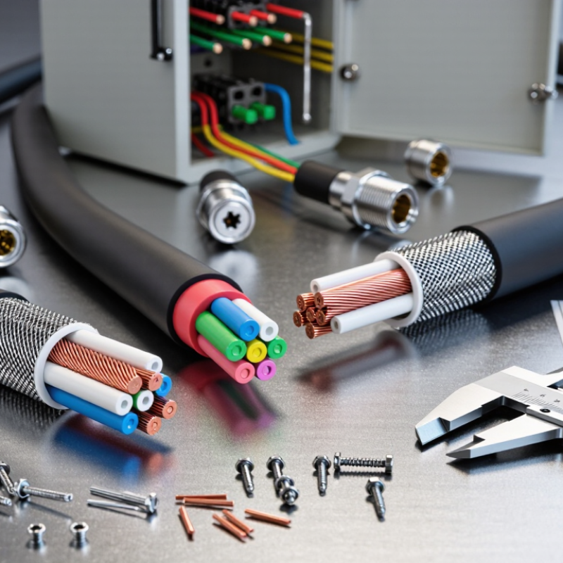
A cable assembly is a finished group of wires, connectors, terminals, and protective materials. It transfers power, signals, or data between two points. Unlike loose cable, it arrives prepared for installation. Each end may include a connector, crimped terminal, plug, or custom contact. The outer jacket protects conductors from abrasion, moisture, heat, and repeated movement.

Its design depends on the working environment. A control cabinet may need compact wiring and clear identification. A machine arm may require flexible conductors with a controlled bend radius. Outdoor equipment needs suitable sealing and resistance to sunlight or temperature changes. Electrical current, voltage, signal frequency, cable length, and connector compatibility also matter. Small details can cause large problems.

Check the pin arrangement carefully. Confirm conductor size and insulation ratings. Ask for continuity, insulation, and crimp-pull test records when reliability matters. A cable can look perfect and still fail under vibration. Field technicians often find that poor strain relief causes damage near the connector, not in the middle of the cable. That detail is easy to miss.

No selection method is flawless. Specifications may be incomplete, and real installation conditions can differ from drawings. Leave enough routing space, but avoid loose loops that catch on moving parts. Review samples before approving volume production. Test the assembly in its actual installation position whenever possible.

Main Parts and Common Cable Assembly Types

What Is a Cable Assembly and How to Choose One?

A cable assembly combines conductors, insulation, terminals, connectors, shielding, and protective covering. Each part affects safety and performance. Copper conductors carry power or signals. Insulation separates them and controls voltage resistance. Connectors create removable electrical interfaces, while terminals secure wires inside those connectors. A braided shield can reduce electromagnetic interference. The outer jacket protects against abrasion, oils, moisture, and temperature changes. Strain relief is small but important. It prevents repeated bending from pulling directly on the contact points. Labels also help technicians identify cables during installation and maintenance.

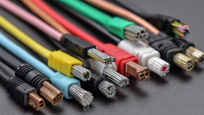
Common cable assembly types include single-ended leads, double-ended cables, ribbon cables, coaxial cables, twisted-pair cables, and multi-conductor harnesses. Coaxial designs suit controlled high-frequency signals. Twisted pairs help limit noise between signal conductors. Ribbon cables fit compact, organized layouts. Harnesses combine several circuits and may include branches, clips, sleeves, or protective tubing. Overmolded assemblies provide stronger sealing and better mechanical support. Custom assemblies often match unusual lengths, connector positions, or installation routes.

Selection should begin with the application, not appearance. Check voltage, current, signal frequency, conductor size, bend radius, and required length. Then review temperature, vibration, moisture, chemical exposure, and available space. A cable that works on a test bench may fail beside a hot motor. The common mistake is choosing a connector first. It can force awkward routing later. Inspect contact quality, pull strength, shielding continuity, and clear identification. Do not trust a neat drawing alone. Real installations are less forgiving. Sometimes the specification itself needs questioning.

How Cable Assemblies Are Designed and Manufactured

A cable assembly is designed around a real connection, not a drawing alone. Engineers begin by defining voltage, current, signal speed, bending radius, length, and installation space. These details determine conductor size, insulation type, shielding, and connector selection. A cable for a moving machine needs different construction from one installed inside a control cabinet.

The design normally develops through a wiring diagram, a dimensional drawing, and a controlled parts list. Conductors are cut to length, stripped carefully, and terminated with specified crimp force. Poor stripping can damage strands and reduce reliability. It happens more often than expected. The assembly may also include braided shields, heat-shrink tubing, labels, backshells, or protective sleeving. Each feature should support a measured requirement, rather than appearance.

Manufacturing quality depends on repeatable processes and documented inspection. Technicians check wire length, contact position, polarity, and connector locking. Pull-force testing helps confirm that crimps can withstand installation stress. Continuity testing identifies open circuits, while insulation or high-voltage testing may be required for suitable applications. Environmental tests can examine vibration, moisture, temperature cycling, and repeated flexing. Traceable materials and inspection records make faults easier to investigate. A prototype often exposes practical problems, such as a bend that is too tight or a label hidden after installation. Revising the design at this stage is cheaper than correcting field failures. However, test results must reflect actual use; a perfect bench sample can still perform poorly in service.

Key Specifications for Comparing Cable Assemblies

What Is a Cable Assembly and How to Choose One?

A cable assembly combines conductors, insulation, connectors, and protective materials into one tested unit. Choosing one requires more than matching connector shapes. Compare voltage, current, impedance, and operating temperature first. A cable carrying power needs different construction from a high-speed data cable. Check the conductor size, shielding method, bend radius, and overall length. Small differences can affect heat, signal quality, and service life.

Connector compatibility matters, but it is not the only concern. Verify pin layout, contact material, locking method, and ingress protection rating. For moving equipment, review flex-life data and jacket resistance against oil, moisture, and abrasion. In practical installations, I have seen a cable fail because its bend radius was ignored. The specification looked correct on paper. The application was not.

Tips: Create a comparison table before requesting samples. Record current, voltage, frequency, temperature, and movement conditions. Ask for test reports, dimensional drawings, and continuity results. Do not rely on appearance alone. A thicker cable may offer better protection, but it can also restrict movement. Leave reasonable length for routing, yet avoid loose loops near heat sources. If the environment is uncertain, test a sample under realistic conditions. That step can expose assumptions early.

A Step-by-Step Guide to Choosing the Right Assembly

What Is a Cable Assembly and How to Choose One?

A cable assembly combines conductors, connectors, insulation, shielding, and protective jackets. It transfers power or signals between equipment. The right assembly should match the application, not just the connector shape. Check voltage, current, signal frequency, operating temperature, and expected movement. A cable inside a fixed control cabinet faces different stress than one bending beside a motor.

A Step-by-Step Guide to Choosing the Right Assembly

Start by documenting each connection point. Measure the required length, including bends and service loops. Then select the conductor size from the current load and allowable voltage drop. Choose insulation for heat, moisture, chemicals, and abrasion. Confirm connector compatibility, locking method, and contact material. For high-speed signals, review impedance, shielding, and grounding details. Test samples under realistic conditions before approving production. I have seen neat specifications fail because installation space was ignored. Measure the route twice. Small errors become expensive rework.

Tips: Leave practical strain relief near every connector. Avoid forcing a cable around sharp corners. Label both ends before installation. Ask for continuity, insulation, and pull-test records when reliability matters. A flexible jacket may seem ideal, but excessive softness can reduce protection. That choice deserves another review. Keep drawings, test results, and revision dates together. This makes future maintenance clearer and supports consistent quality.

What Is a Cable Assembly and How to Choose One? - A Step-by-Step Guide to Choosing the Right Assembly

Step Selection Dimension What to Define Typical Options Practical Selection Guidance
1 Function and Application Identify what the cable assembly must connect and how it will operate. Power, signal, data, sensor, control, audio/video, or mixed-purpose connection Start with the equipment interface, operating environment, installation method, and expected service life.
2 Electrical Requirements Specify voltage, current, frequency, signal type, and impedance where applicable. DC or AC power; analog or digital signal; low-speed or high-speed data Choose conductors and contacts with ratings above the expected electrical load, while following the applicable safety standard.
3 Conductor Material and Size Select conductor material, cross-sectional area, and strand construction. Copper or tinned copper; solid or stranded; AWG or mm² sizes Stranded copper generally provides better flexibility. Larger conductors reduce voltage drop and heating but increase size and cost.
4 Cable Construction Define the number of conductors, pair arrangement, twist, drain wire, and overall jacket. Single-core, multi-core, twisted pair, coaxial, ribbon, or hybrid construction Use twisted pairs for improved differential-signal performance and coaxial construction when controlled impedance is required.
5 Insulation and Jacket Match the dielectric and outer jacket to temperature, chemicals, moisture, abrasion, and flame requirements. PVC, polyethylene, polyurethane, fluoropolymer, silicone, or thermoplastic elastomer PVC is common for general use; polyurethane is often selected for abrasion and flexing; fluoropolymers suit demanding temperature or chemical conditions.
6 Temperature Range Determine the minimum and maximum continuous operating temperatures and any short-term extremes. Standard indoor range; extended-temperature; high-temperature; low-temperature service Do not select a cable from ambient temperature alone; include heat from current flow, nearby components, and enclosure conditions.
7 Shielding and EMI Control Assess susceptibility to electromagnetic interference and the amount of electrical noise generated. Unshielded; foil shield; braided shield; foil-and-braid combination Use shielding when signal integrity or emissions are concerns. Define how the shield will be terminated to maintain an effective path.
8 Connector and Contact Type Specify mating interface, contact count, contact arrangement, locking method, and keying. Wire-to-wire, wire-to-board, circular, rectangular, board-edge, or custom connector Confirm pinout, mating cycles, contact ratings, polarization, retention, and available space before finalizing the connector.
9 Termination Method Choose how conductors will be attached to contacts or equipment. Crimp, solder, screw terminal, insulation displacement, or molded termination Crimped terminations provide consistent mechanical performance when the correct tooling and verified crimp dimensions are used.
10 Mechanical Movement Define whether the assembly is fixed, occasionally flexed, continuously flexed, twisted, or exposed to vibration. Static installation; occasional flex; drag-chain or robotic movement; torsional movement Use flexible stranding, suitable jacket material, strain relief, and the manufacturer’s specified bend radius for moving applications.
11 Length and Bend Radius Specify finished length, allowable tolerance, routing path, and minimum bend radius. Fixed lengths; custom lengths; straight or right-angle exits Avoid tight bends near connectors. The required bend radius depends on cable construction and should be verified from the applicable cable specification.
12 Environmental Protection Determine exposure to water, dust, oils, chemicals, sunlight, salt spray, impact, and vibration. Indoor; outdoor; washdown; oil-resistant; UV-resistant; sealed or ruggedized Select sealing, jacket, backshell, and strain-relief features based on the complete installation environment, not just the connector body.
13 Regulatory and Safety Needs Identify required insulation, flammability, environmental, and industry compliance criteria. RoHS or REACH material requirements; flame performance; application-specific electrical safety requirements Document the required regulations and verify that the complete cable assembly, including connectors and overmolds, meets them.
14 Testing and Quality Checks Define inspection, electrical testing, dimensional checks, and acceptance criteria. Continuity; polarity; insulation resistance; dielectric withstand; visual and pull testing A production test plan should match the assembly’s risk level and include documented pinout, wire preparation, crimp, and final inspection requirements.
15 Final Design Review Confirm performance, fit, reliability, manufacturability, availability, and total cost. Prototype; pilot production; standard configuration; custom configuration Review drawings, cable schedules, pinouts, tolerances, test records, and service conditions before approving the final assembly.
Key takeaway: The right cable assembly balances electrical performance, mechanical durability, environmental resistance, connector compatibility, safety requirements, and total installation cost.
Go to Top