
How to Choose the Right Transformer Core Types?
Choosing the right Transformer Core Types is a practical decision, not a simple catalog comparison. Core material affects efficiency, heat, size, cost, and long-term stability. A ferrite core may suit a high-frequency switch-mode supply. Laminated silicon steel often performs better at lower power frequencies. Powdered iron can provide useful energy storage in certain inductive applications. Nanocrystalline materials may reduce losses, but their price and processing requirements need careful review.
A reliable selection begins with operating frequency, maximum flux density, current, voltage, and required isolation. Temperature also matters. A core that performs well at 25°C may behave differently inside a sealed enclosure. Engineers should check manufacturer curves, not rely on attractive headline ratings. Small details count. Winding window size, insulation clearance, air gaps, and mechanical vibration can change the final result. Test the complete magnetic assembly.
There is no universal best core.
In real design reviews, calculations sometimes look correct while the prototype still runs hot. That outcome deserves investigation, not excuses. Leakage inductance, winding resistance, assembly pressure, and unexpected harmonics may explain the difference. Designers should compare measured temperature rise with predicted losses and document every assumption. Standards, supplier data, and qualified engineering review improve confidence. Still, material data can vary between manufacturers, and some published values require interpretation. The best Transformer Core Types balance electrical performance, manufacturability, safety, availability, and lifecycle cost. A cautious decision usually outperforms an impressive specification.
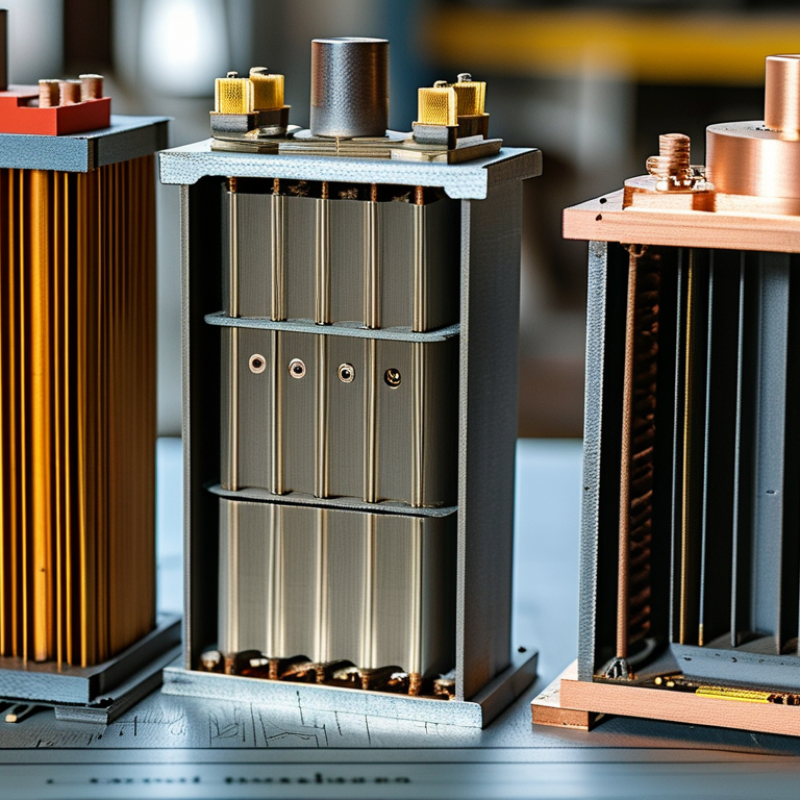
Understanding the Role of a Transformer Core
A transformer core is the magnetic path that allows energy to move between windings. Its role is more than holding copper coils in place. The core concentrates magnetic flux, reduces leakage, and helps control voltage conversion. Without a suitable core, even carefully designed windings may produce heat, noise, or unstable output.
In practical testing, core material is often the first variable I examine. Ferrite usually suits high-frequency transformers because it limits eddy-current losses. Laminated steel works well at lower frequencies and higher power levels. Powdered cores can offer useful distributed air gaps for energy storage. Shape matters too. An E-shaped core may simplify assembly, while a toroidal core can reduce magnetic leakage. These choices affect size, cooling, insulation distance, and manufacturing cost.
Do not choose by power rating alone. Frequency, waveform, temperature, and duty cycle can change the result. A core that performs well in a laboratory may run hotter inside a sealed enclosure. I have also seen designs fail because the air gap was treated as a minor detail. It was not. Engineers should verify flux density, core loss, winding temperature, and audible vibration through measured tests. Calculations provide direction, but measurements reveal the inconvenient parts. A small safety margin is wise, although an oversized core can increase cost and reduce efficiency. The right transformer core type is therefore the one that supports the complete operating system, not just the winding ratio.
| Core Type | Typical Magnetic Material | Common Frequency Range | Key Characteristics | Main Advantages | Important Limitations | Typical Applications | Selection Considerations |
|---|---|---|---|---|---|---|---|
| Laminated Silicon-Steel Core | Grain-oriented or non-oriented electrical steel, assembled from insulated laminations | Usually 50–60 Hz for power transformers; higher frequencies are possible with suitable designs | Thin steel laminations reduce circulating eddy currents. Grain-oriented steel is commonly used where the main flux direction is predictable. | High permeability at power frequency, mature manufacturing methods, strong mechanical structure, and good suitability for medium- and high-power transformers | Heavier and larger than high-frequency ferrite designs; core loss increases if the core is over-fluxed or operated above its intended frequency | Utility transformers, distribution transformers, industrial power transformers, and low-frequency isolation transformers | Choose it when power level, mechanical strength, and 50/60 Hz efficiency are more important than minimum size and weight |
| Ferrite Core | Soft manganese-zinc ferrite or nickel-zinc ferrite | Approximately 10 kHz to several hundred kilohertz, depending on grade, temperature, and flux density | High electrical resistivity greatly reduces eddy-current loss at high frequency. Ferrite has relatively low saturation flux density compared with electrical steel. | Low high-frequency loss, low weight, compact size, and good performance in switch-mode power conversion | Lower saturation flux density; brittle material; performance can decline with temperature and excessive DC bias | Switch-mode power supplies, high-frequency transformers, electronic converters, gate-drive transformers, and electromagnetic interference filters | Choose a material grade based on operating frequency, temperature, allowable core loss, peak flux density, and DC bias conditions |
| Amorphous Metal Core | Rapidly solidified amorphous metallic alloy, commonly based on iron with alloying elements | Primarily 50–60 Hz power applications | Its non-crystalline structure can provide low hysteresis loss at power frequency. The ribbon material is very thin and usually formed into a wound core. | Very low no-load loss compared with many conventional power-frequency steel cores, helping reduce standby energy consumption | Material can be more difficult to process; cores may be more sensitive to mechanical stress and may require careful handling and design | Energy-efficient distribution transformers and applications where no-load loss is a major design concern | Choose it when lifetime energy savings and low no-load loss justify potentially higher manufacturing and handling requirements |
| Nanocrystalline Core | Nanocrystalline soft magnetic alloy with very fine crystalline grains | Typically from several kilohertz to hundreds of kilohertz, depending on material grade and design | Combines high permeability, relatively high saturation flux density, and low loss across a broad frequency range. | Excellent permeability, compact magnetic components, low core loss, and strong performance in common-mode filtering and high-frequency power conversion | Higher material cost than many ferrites; sensitive processing and thermal design may be required; available shapes and sizes can be more limited | Common-mode chokes, current transformers, high-frequency transformers, resonant converters, and power-factor-correction magnetics | Choose it when high permeability, low loss, compact size, or wide-band performance is more important than the lowest material cost |
| Powdered-Iron Core | Iron powder distributed in an insulating binder | Approximately 10 kHz to several hundred kilohertz, depending on composition and application | Distributed air gaps provide useful energy storage and make the core suitable for inductive components carrying DC current. | Good DC-bias tolerance, distributed-gap behavior, and availability in toroidal and other useful shapes | Core loss can be higher than ferrite at some frequencies; permeability is lower and temperature characteristics vary by material type | Power inductors, energy-storage chokes, output filters, and some high-frequency transformer designs | Choose it when energy storage and DC-bias performance are more important than achieving the lowest possible high-frequency loss |
| Sendust Core | Powdered alloy typically containing iron, silicon, and aluminum in an insulating binder | Approximately 20 kHz to several hundred kilohertz, subject to material grade and flux waveform | Has distributed air gaps, moderate permeability, low audible magnetostriction, and generally lower core loss than some traditional powdered-iron materials. | Good energy-storage capability, low audible noise, and useful DC-bias stability | Usually more expensive than basic powdered iron; maximum flux density and frequency capability depend strongly on the selected grade | Output inductors, boost converters, buck converters, power-factor-correction inductors, and filter chokes | Choose it for compact energy-storage inductors where low acoustic noise and controlled DC-bias behavior are important |
| C-Cut or U-I Laminated Core | Laminated electrical steel, ferrite, or other magnetic material formed into matched core sections | Power-frequency designs with electrical steel; high-frequency designs with ferrite or other suitable materials | Preformed sections simplify winding assembly and can provide a controlled, accessible magnetic path. The joint design influences reluctance and loss. | Convenient assembly, adaptable window dimensions, and serviceable construction for some medium- and high-power designs | Air-gap and joint quality can affect magnetizing current, noise, and efficiency; larger assemblies may be less compact than toroidal designs | Power transformers, audio transformers, inverter transformers, welding equipment, and industrial magnetic components | Choose it when winding access, custom geometry, mechanical integration, or repairability is important |
| Toroidal Core | Electrical steel, ferrite, amorphous metal, nanocrystalline alloy, or powdered magnetic material | Depends on the material: typically 50–60 Hz for steel and from kilohertz to hundreds of kilohertz for ferrite or powder materials | A closed magnetic path minimizes external leakage flux. The winding is distributed around the ring, producing a compact and efficient structure. | Low leakage field, high magnetic utilization, compact shape, and often low audible hum when correctly designed | Winding can be labor-intensive; insulation and thermal management may be more difficult; adding a controlled air gap is not always convenient | Audio transformers, medical and laboratory equipment, power supplies, current transformers, and electromagnetic interference filters | Choose it when low stray magnetic field, compact packaging, and efficient use of the magnetic path are key requirements |


© 2023 JEM Electronics, Inc. – United States Cable Assembly. All rights reserved.