
Blog

How to Choose a 90° Peel Strength Tester?

Choosing a 90° Peel Strength Tester is not simply a matter of comparing prices and maximum loads. The instrument must match your materials, test method, and production risks. A flexible film, coated paper, adhesive label, and medical packaging may require different fixtures and force ranges.

In practical testing, small details often change the result. Sample width, peel angle, backing stiffness, and crosshead speed all matter. Check whether the tester supports relevant methods, such as ASTM D6862 or ISO 8510-1. These standards provide useful direction, but they do not remove the need for careful sample preparation. A poorly aligned strip can create uneven peeling and misleading data.

Look beyond the display.

A reliable 90° Peel Strength Tester should offer a stable frame, suitable load cells, controlled speed, and clear data recording. Software should show peel-force curves, average force, peak force, and test conditions. Calibration records should be traceable, with service support available after installation. Ask the supplier to demonstrate repeatability using your actual material, not only a perfect sample.

Environmental control may also be important. Temperature and humidity can affect adhesive behavior, especially during long production runs. A tester that works well in a quiet laboratory may perform differently beside a busy coating line. The cheapest option can become expensive when fixtures wear quickly or results cannot be defended during an audit. Still, advanced features are not always necessary. Choose what your quality process can use consistently. That decision may require more reflection than expected.
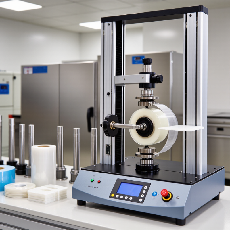
How to Choose a 90° Peel Strength Tester?

Define 90° Peel Strength and Its Units: N/25 mm Under ASTM D3330

How to Choose a 90° Peel Strength Tester?

90° peel strength measures the force required to separate an adhesive tape from a surface at a right angle. The usual reporting unit is N/25 mm, meaning force normalized to a 25 mm-wide strip. One N/25 mm equals 40 N/m. This unit makes results easier to compare across laboratories. ASTM D3330 is widely referenced for pressure-sensitive tape testing, but its primary methods use a 180° peel angle. A 90° test should therefore document the fixture, peel angle, backing material, and test speed. ASTM D6862 may provide a more suitable reference for certain 90° adhesive evaluations.

Choose a tester with a rigid 90° peel arm, stable load-cell control, and a clear force-versus-distance record. ASTM D3330 commonly uses a 25 mm specimen width and a nominal peel rate near 300 mm/min. Small deviations can change the measured peak force. The International Organization for Standardization also emphasizes controlled conditioning in peel testing. Temperature, humidity, dwell time, and substrate roughness must be recorded. In practical laboratory work, the first ten millimeters often show unstable force. Exclude the startup region only when your method permits it. Perfect curves are uncommon.

Tips: Calibrate the load cell before testing. Use at least five specimens when variability matters. Report the mean, standard deviation, and failure mode. Cohesive failure, adhesive failure, and backing stretch should not be treated as identical results. A tester that displays only one peak value may hide important evidence.

References: ASTM D3330, ASTM D6862, and ISO 8510-2.

Match Load-Cell Capacity to the Expected Peel Range and Resolution

How to Choose a 90° Peel Strength Tester?

The load cell should match the expected peel range, not simply the strongest possible force. Estimate the sample’s peak peel force from previous tests, product specifications, or small preliminary trials. A practical target is to keep normal readings within the middle portion of the load-cell capacity. This usually provides better resolution and more stable results.

Too large a load cell can hide small differences between samples. That matters when comparing coatings, labels, films, or adhesive liners. For example, a 2 N variation may be important in a low-force test but nearly invisible on an oversized sensor. Too small is risky. Sudden adhesive release can create a sharp force spike and overload the system.

Leave room for peaks.

Check the tester’s resolution, accuracy, overload protection, and calibration procedure together. Resolution alone does not guarantee trustworthy data. The fixture must also hold the specimen at a true 90° angle, while the peel speed remains consistent. Small alignment errors can change the measured force more than expected.

Do not choose capacity from one perfect sample. Production materials vary with temperature, dwell time, backing stiffness, and surface cleanliness. A capacity that works in the laboratory may fail during routine quality checks. This is where selection becomes less certain. Review actual force curves, not only average values, and confirm the final range with a qualified test-equipment specialist. Calibration records and traceable verification should support every important comparison.

Verify 90° Angle Accuracy, Peel Speed, and Grip Alignment

How to Choose a 90° Peel Strength Tester?

Verify 90° Angle Accuracy, Peel Speed, and Grip Alignment

A reliable 90° peel tester begins with angle control. The specimen should leave the substrate at 90°, not 87° or 94°. Even small deviations can change measured force, especially with stretchy films. ASTM D3330 Method F and FINAT FTM 2 commonly use a 25 mm specimen width and a 300 mm/min peel speed. Choose equipment that records these settings digitally and maintains them during testing.

Peel speed needs equal attention. A drifting motor can create a misleading force curve. Watch the first 50 mm of travel. The line should look stable, without sudden spikes caused by jerky movement. Grip alignment matters too. The upper grip must stay centered above the peel path. If the strip twists, edge loading may increase the result. ISO 8510-2 also emphasizes controlled geometry for flexible adhesive materials. Standards help, but they do not remove every testing error.

Tips: Place a small alignment mark across the specimen and grip. Check whether both marks stay level during peeling. Ask for calibration records, angle verification data, and speed-tolerance results. A tester may pass a basic inspection yet still produce inconsistent readings. That uncomfortable possibility deserves attention. Run five repeated tests, compare the force curves, and investigate variation before trusting one impressive number.

How to Choose a 90° Peel Strength Tester? - Verify 90° Angle Accuracy, Peel Speed, and Grip Alignment
Selection Profile Typical Peel-Force Range Recommended Load Cell 90° Angle Accuracy Peel-Speed Range Speed Accuracy Grip Alignment Requirement Useful Test Length Recommended Verification Method Suitable Applications
Routine Quality Control 0.2–100 N 100 N, with a resolution of at least 0.01 N 90° ± 1.0° 50–300 mm/min Within ±2% of the set speed Specimen and grip centerlines aligned within 1.0 mm Up to 300 mm Check the angle with a calibrated digital inclinometer and verify speed over a measured travel distance Adhesive tapes, labels, films, and packaging seals
General Laboratory Testing 0.05–500 N 500 N, with a resolution of at least 0.05 N 90° ± 0.5° 10–500 mm/min Within ±1% of the set speed Parallel grip faces; lateral offset no greater than 0.5 mm Up to 500 mm Use a calibrated angle block or inclinometer, a displacement check, and a grip-parallelism gauge Coated substrates, flexible laminates, medical tapes, and protective films
Low-Force Adhesive Testing 0.005–50 N 50 N, with a resolution of at least 0.005 N 90° ± 0.5° 1–300 mm/min Within ±1% of the set speed Self-aligning grip or guided fixture to minimize bending and twisting Up to 300 mm Perform zero-load stability, angle, speed, and alignment checks before each test series Low-tack labels, skin-contact adhesives, thin films, and release liners
High-Force or Reinforced Materials 1–2,000 N 2,000 N, with a resolution of at least 0.2 N 90° ± 1.0° 10–250 mm/min Within ±2% of the set speed Rigid fixture with reinforced mounting; offset no greater than 1.0 mm Up to 500 mm Inspect fixture deflection under load and confirm angle under the expected working force Reinforced tapes, construction membranes, heavy laminates, and bonded composites
Standards-Based Research Testing Selected according to specimen and adhesive system Choose a capacity so the expected peak force is between 10% and 90% of full scale 90° ± 0.5° or tighter when required by the test method Programmable from 1–500 mm/min Within ±1% of the set speed across the selected range Grip alignment verified before testing and maintained throughout the peel stroke At least 500 mm, subject to specimen dimensions Document angle, speed, force calibration, fixture condition, specimen width, and conditioning procedure Method development, comparative studies, and testing aligned with ASTM D3330 or ISO 8510-1 principles
Automated Repetitive Testing 0.05–1,000 N Selected interchangeable load cells covering the expected force range 90° ± 0.5° during the complete test stroke 10–500 mm/min with programmable presets Within ±1% of the programmed speed Fixed reference fixture, repeatable specimen positioning, and automatic alignment check Up to 1,000 mm Use scheduled calibration, automatic travel verification, and periodic fixture repeatability checks Production audits, batch comparison, and high-volume adhesive product evaluation

Standardize Specimen Width and Conditioning at 23 ± 2°C and 50 ± 5% RH

How to Choose a 90° Peel Strength Tester?

A reliable 90° peel test begins before the specimen reaches the tester. Define the specimen width in the method, then cut every strip with a sharp, calibrated die. Small width differences can distort force-per-width calculations. A 25 mm strip should not quietly become 24.5 mm. Measure several pieces with a precision ruler or digital gauge.

Condition specimens at 23 ± 2°C and 50 ± 5% relative humidity before testing. Use a controlled chamber, not an open office near a window. Keep samples flat, separated, and protected from dust. Follow the relevant standard for conditioning time, because adhesive systems may need longer equilibration. Record temperature and humidity during the test. Conditions matter.

Choose a tester with stable 90° geometry, adjustable peel speed, and a load cell suited to the expected force. Check that the roller, clamp, and pulling axis remain aligned. Misalignment can create uneven peeling, visible as a wavering force curve. Experienced technicians inspect the first few traces rather than trusting one numerical result. That habit is useful.

One weakness remains. Conditioning may look precise while the adhesive surface changes during handling. Limit exposure time after removal from the chamber, and document it. Recheck specimen width after cutting. A neat procedure can still hide variation. Calibration records, operator training, and clear rejection criteria make the data more defensible.

Assess Calibration, Data Reporting, Safety, and ISO 8510-2 Compliance

How to Choose a 90° Peel Strength Tester?

Calibration should be your first serious checkpoint. Ask for traceable calibration records for the load cell and displacement system. The instrument should maintain a true 90° peel path under load. Small alignment errors can distort results. In practical laboratory work, I would inspect the fixture with a square before testing. Confirm the peel rate, force range, and measurement resolution. A useful tester should also support routine verification between formal calibrations.

Data reporting must match ISO 8510-2 requirements and your internal procedure. The software should record specimen dimensions, adhesive type, peel rate, conditioning temperature, and test results. Report force using a clearly stated unit, such as N/25 mm, when applicable. Include average force, variation, and the selected evaluation region. Save raw curves, not only final values. A neat graph can still hide unstable peeling. Failure descriptions matter too. Note adhesive failure, cohesive failure, substrate damage, or irregular separation.

Safety deserves equal attention. Look for guarded moving parts, an accessible emergency stop, and controlled specimen clamping. Operators should not place fingers near the moving carriage. Check whether the fixture handles narrow or flexible samples securely. A poorly held specimen can twist, slip, and produce misleading data. ISO compliance is not created by a label alone. Review the complete test method, equipment settings, calibration evidence, and reporting format. I would also test several reference samples before approval. The result may reveal weaknesses in the procedure itself.

How to Choose a 90° Peel Strength Tester?

Assess calibration, data reporting, safety, and ISO 8510-2 compliance

A suitable 90° peel strength tester should provide traceable force calibration, controlled peel speed and angle, clear data reporting, effective operator protection, and test settings aligned with ISO 8510-2. The chart compares the practical importance of these selection dimensions on a five-point assessment scale.

Go to Top